This page is sponsored by
|
This page is sponsored by
|
My
Home-Made Bob Beck Magnetic Pulser (Thumper)
Based on the Designs by Chris Gupta and Bil Green
If you made it to this web page, you most likely have already been researching the Bob Beck Protocol. If you have no knowledge of electronics and are wanting to build your own pulser, I recommend thoroughly going over Chris Gupta's Pulser page first and then coming back here to fill in the blanks. Here I offer photographs of my very first fully manual Beck style mag pulser, along with additional information that may be of assistance to anyone wanting to build their own device.
Bob Beck Protocol Information: If you would like to learn more about Robert Beck and the Beck Protocol, you can view several Google Videos by clicking on the following Link - Beck Video. Beyond these videos, there is a wealth of information on the Internet about the Bob Beck Protocol. In a nutshell however it implies a four process system involving blood electrification, electromagnetic pulse, colloidal silver and ozonated water. If you are experiencing cancer, HIV, lupus, Candida or one or more of a host of other ailments, it would be worth your time to research this health process. Also, you can download the accompanying manual that was handed out to participants of the Bob Beck Lecture ("Take Back Your Power" (1MB PDF). I have searched high and low for this and finally found the complete document.
Imprtant technical information provided by Russ Torlage of Sota Instruments regarding the construction of electromagnetic pulsers can be found by clicking on this link.
The information I provide on this web page is an account of what I have learned in the process of studying Beck devices and building my own units for my own experimentation purposes. I assume no responsibility for anything one might do with the information provided on this web page. Please view any explanations as hypothetical and not as instructions to be followed.
Lethal Electric Shock Hazard!
This device uses 120V AC current and a powerful capacitor that charges up to 360V. If
this device is not built in a safe manor, there can be a risk of
lethal electric shock. It
would advisable for individuals that are unfamiliar with electronics,
to have someone
like a TV repairman build this device for them. PLEASE
PLEASE PLEASE be absolutely present, mindful and cautious when
working around exposed capacitors. As you will
read below, even a shock by a single capacitor from a disposable
camera, can be extremely unpleasant. A professor at
Pen Engineering jokingly recommended that I keep one hand in my
pocket. In other words, keeping one hand in my pocket would prevent
an electric shock from traveling across my heart!
Looking on the bright side however, Chris Gupta told me that many people have successfully built and are using this device based on his schematic. I'm just asking those that are intending to build this machine, to use safe practices when working around exposed capacitors and hot electrical wires.
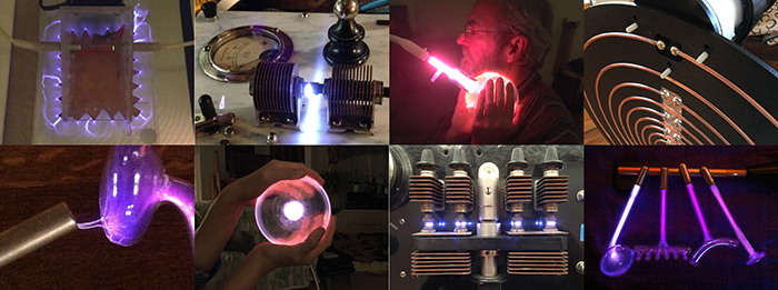
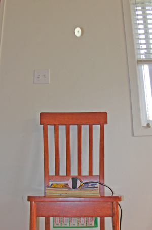
Please take a close look at the all of the photos and images below before reading on. As I don't provide a lead-in, reviewing the images will help you to understand what I'm talking about.
All measurements are in Inches.
Plastic Box Outside Dimensions:
approximately 2-3/8 X 4-1/4 X 7-3/8
Using 1/2 inch #4 beveled machine screws I fastened a 1/8 inch Plexiglas
sub-floor to the bottom of the box in order to allow for the
attachment of the Terminal Contact Bars and the home-made bracket for
the SCR. The sub-floor also provides an insulated surface
for the circuit components to be mounted to. Screws were counter sunk
into the outside-bottom of the plastic box and fastened on the inside
with a lock washers and nuts. After all components were soldered and
attached to the sub-floor, the sub-floor was then fastened to the ends
of the four screws coming up from the bottom of the box and again fastened
with nuts and lock washers.
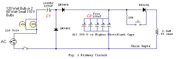
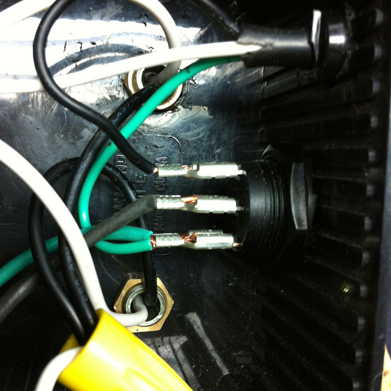
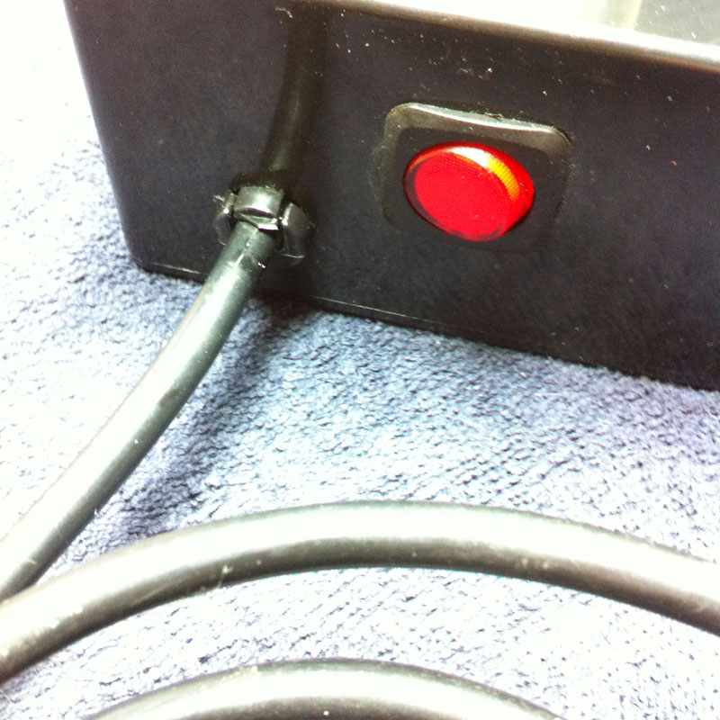
Looking at Chris Gupta's Mag Pulser circuit, Gupta has the on/off switch on the negative or neutral side circuit. It should be switching the hot lead not the neutral lead! First the On/Off switch and then the bulbs are on the positive side of the circuit. In electrical circuits, generally it is always the hot lead (+) that is switched.
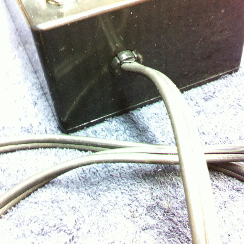
Implementing a Strain Relief:
Strain reliefs are essential for electrical safety. They prevent cables from
being ripped out of a circuit in the event an electrical device gets
dropped or e.g., should someone trip over an electrical chord.
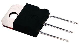
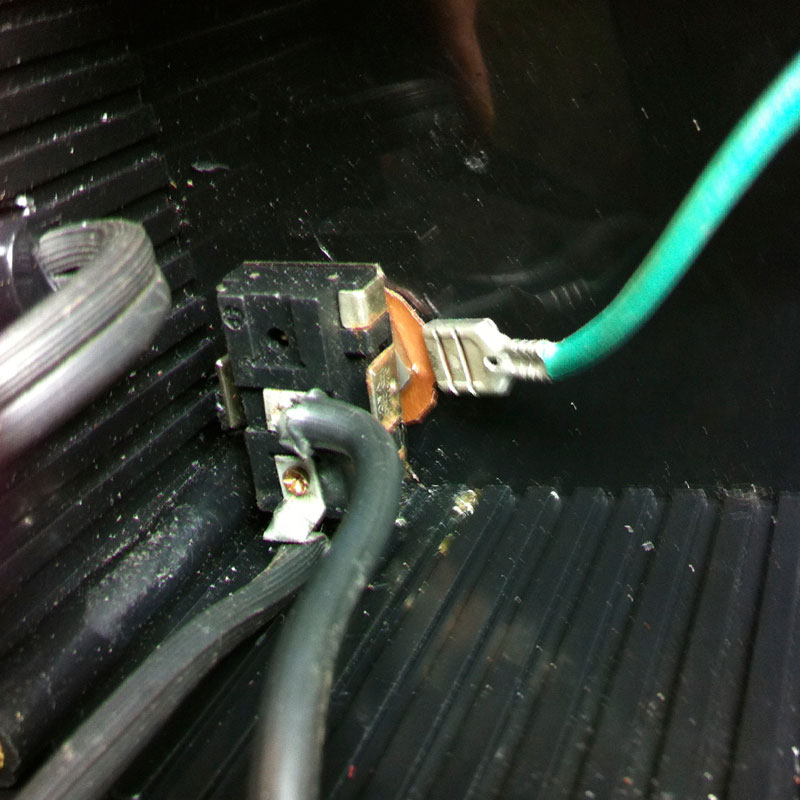
The SCR:
The SCR (Silicon Controlled Rectifier)
and has three contacts.

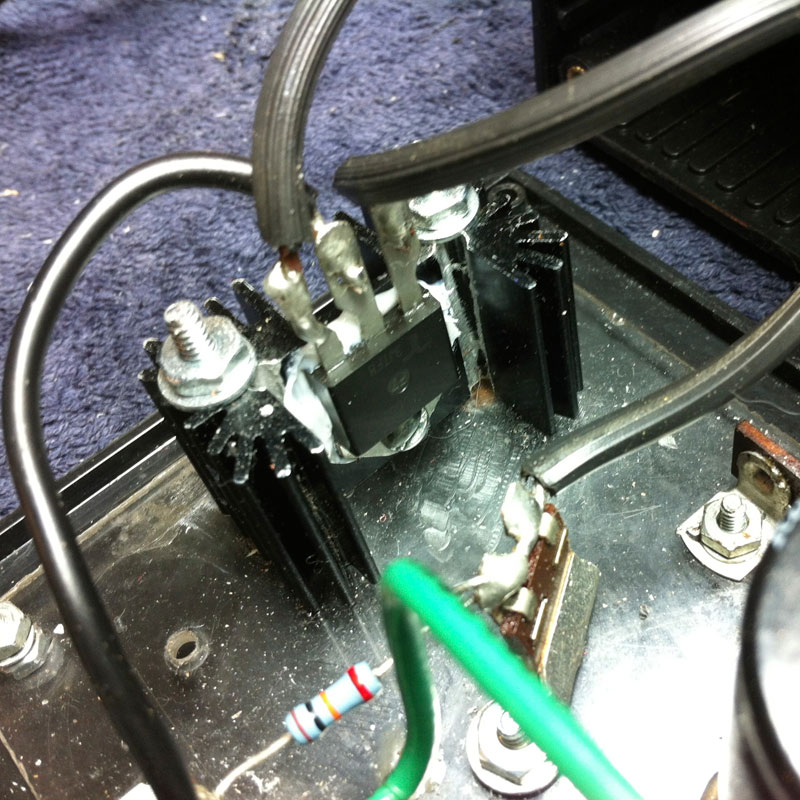
SCR Update November 2016: I have now switched to a new surface mount SCR that is more robust than the Phillips ECG 5529 post mount SCR I was using. The new SCR is the LittleFuse SK065KTP. The LittleFuse SK065KTP SCR is rated for 1000V, has a 41A continuous and an 950A peak amperage rating, which exceeds Gupta's design specs. At least in my searching on the web, I found that S602L that Gupta lists on his schematic actually is not in compliance with his own specifications for that component, as it only has a "Peak Amp" rating of 255A. Gupta told me that component specs vary depending the on manufacturer that makes it. He also told me that a heat sink for the SCR was not necessary. I had already ordered it however, so I went ahead and installed it anyway. New photos of my upgraded EMP based on Chris Gupta's design can be found at the bottom of this page.
Note: The trigger gate on this SCR is 50mA and may not be suitable as is, for use with Gupta's auto-pulsing circuit without installing an additional triggering circuit. This is because the neon bulb may not be able to transmit enough current to trigger the SCR. It's not an issue with the SCR that Gupta recommends, however as I stated above, it is underpowered for this circuit.
Specifications are as follows:
 :
:
LittleFuse SK065KTP SCR
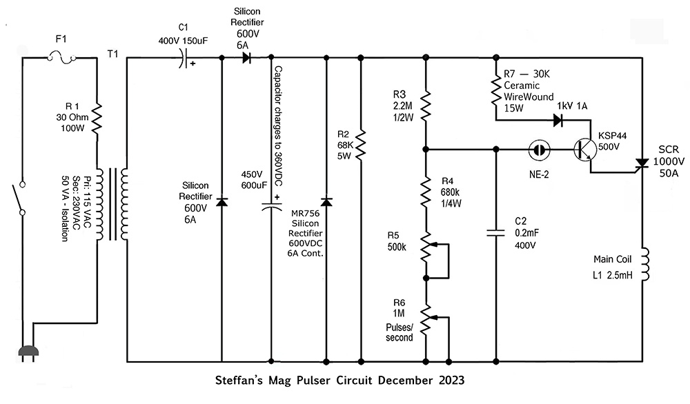
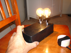
Bulbs and Lamp Holders : In Chris Gupta's design the bulbs act as current limiters and protect the SCR from over-current and short circuiting. Light bulbs were commonly used for this purposes in electrical circuits well into the 1960's. I used candelabra lamp holders as they take up less space and are less bulky. Holes of the appropriate size were drilled into the top of the box about 1 inch in from the edges. The main thing here, is to make sure that the bulbs are not touching when screwed into their sockets. My pulser makes use of two spherical shaped 60W bulbs. The spherical bulbs were more aesthetically pleasing to me than traditional candelabra bulbs. Should a bulb burn out, replace it before continued use. One problem these days is finding incandescent bulbs. Thanks to the Globalist agenda, incandescent light bulbs are becoming harder to find. LED and fluorescent bulbs cannot be used for this purpose. You might ask, can the mag pulser be built without bulbs? The answer is yes and it requires the use of a 50VA 120V/230V -1 isolation transformer. A 100W 30 Ohm power resistor and a cooling fan are also needed to prevent the transformer from over heating. Please see schematic below. This build requires intermediate electronics and soldering skills.
Note: Keep in mind that the bulbs do get hot if you are using the pulser for several minutes at a time.
Inductor Coil: Make your life easier and purchase a beautiful "perfect lay" 2.5mH inductor coil wound with 16 AWG magnet wire from Erse Audio Part #EAC35-16-2500
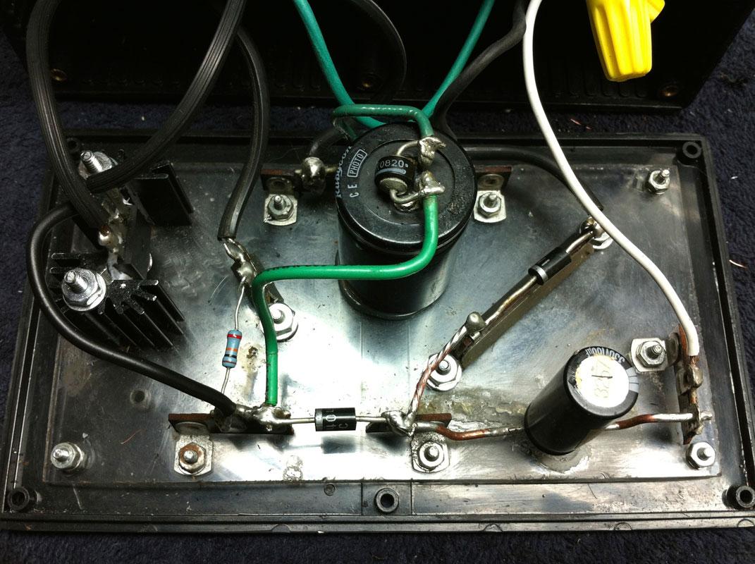
Connecting the Inductor Coil: The inductor coil attaches to the Cathode of the SCR and to the negative 'Contact Bar' of the capacitor bank.
Connecting the Low Current Push To Make" Switch: The "push-to-make" switch attaches to the gate of the SCR and to the 10K resistor. The other end of the 10K resistor attaches to the positive (+) side of the circuit, after the voltage doubler. The voltage doubler is comprised of the capacitor just past the bulbs and the two diodes and converts the 120V house voltage to 260V! I have now switched to 1000V, 10 amp diodes for this location. 1000V diodes are cheap and they add an additional safety measure to protect from unforeseen voltage spikes.
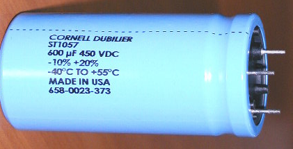
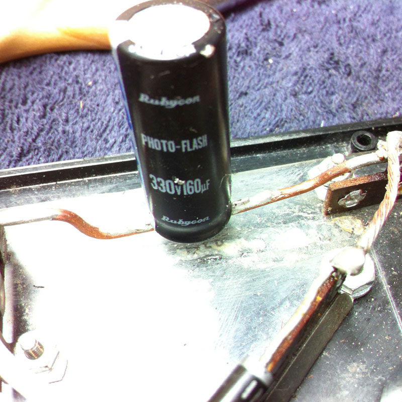
SOMTHING TO THINK ABOUT: Russ Torladge of Sota Instruments claims that having a capacitor with a higher micro-farad rating will not increase the intensity of the magnetic pulse, but rather increases the pulse duration. So perhaps it is better to stick with a single photo flash capacitor (Rubycon 600uF 450V PhotoFlash Capacitor). Russ Torladge of Sota Instruments uses a single 600uF 450V photoflash capacitor in his mag pulser device. Unfortunately, unless one is willing to purchasing 100 capacitors, the Cornell Dubilier ST1057 Strobe Capacitor he uses is unobtainable. I was lucky enough to be able to purchase 3 slightly used caps from Russ for $80 each. Sadly he won't sell them to me anymore. If people want to join forces, perhaps we can round up 50-100 individuals that want the capacitor, maybe we can arrange a joint purchase? I can arrange the order through my account with Newer Technologies. 10 years ago the quote was $4000 ($40 each). Here is a photo of the Cornell Dubilier ST1057 Strobe Capacitor. It is rated for 30,000,000 (30 million) discharges. In other words it's not likely to wear out. Standard photoflash capacitors on the other hand only last about a year depending on use. After that they need to be replaced.
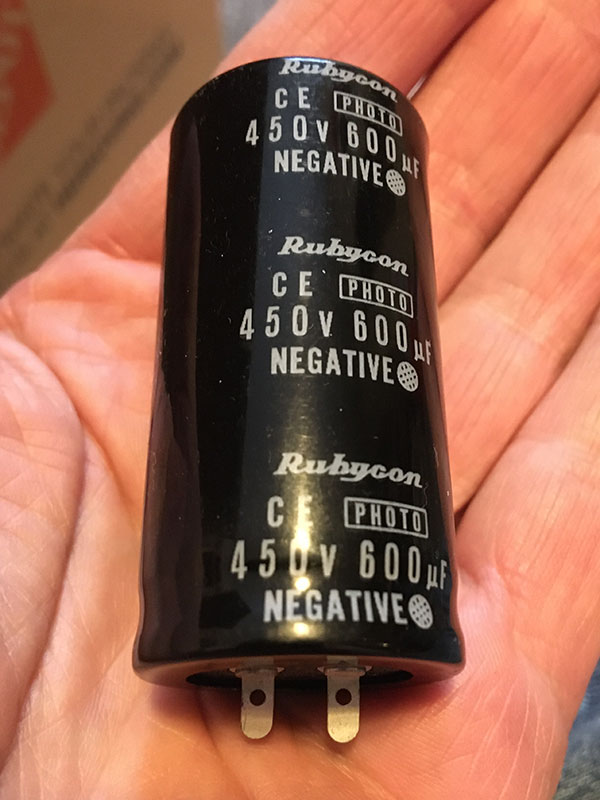
Because the ST1057 is not available to us, the next best option for C2 is a standard Rubycon photoflash rated at 450V 600uF. They sell or about USD $10. If you use your mag pulser for 10 minutes several times per week, you will need to replace the capacitor in about a year. When the capacitor starts to go bad the oil fill housing will begin to swell from internal pressure. Be sure to check it from time to time.
Click on photo to Enlarge
Click here for more information on capacitor charge calculations.
Observing Chris Gupta's circuit design, you see that his schematic calls for one 150V 130uF capacitor for capacitor C1.
The negative terminal of electrolytic capacitors is marked by a stripe running down the side. Two 5-contact, Terminal Contact Bars were used to solder the photo flash capacitors to. As the capacitors need to be connected in parallel, each Terminal Contact Bar has a piece of 14 gage copper wire soldered at each contact across the span of the bar to unify all contacts. The Negative pole of each capacitor is soldered to one contact of the terminal contact bar and the same for the positive side of the capacitors. Be sure the screw mounts are facing toward the outside. Once the capacitors were soldered in place, I marked the hole locations on the Plexiglas sub-floor and drilled the holes. The assembly was then fastened to the sub floor with 1/2 inch #4 Phillips machine screws, lock washers and nuts. See images below.
During testing, when I discharged C2, it sounded like a firecracker going off in my ear and the tips of the 14 gage wire were slightly melted. One does not want to get shocked by that! A jolt like that going across one's heart could be lethal! - Please be careful and always discharge capacitors, even if you think they are not charged. Instructions to build a capacitor discharge tool that will safely discharge a bank of capacitors is outlined above.
Making a Capacitor Discharge Tool: One
can make a capacitor discharge tool with two insulated alligator
clips, about 16 inches of 14 gage stranded wire and a 10,000
ohm, wire-wound, 10 Watt resistor. Solder an insulated alligator
clip to either end of the insulated wire. Then cut the wire about
7 inches from one end, and solder the resistor in place. Now
wrap the resistor and solder points with at least three layers
of ELECTRICAL TAPE. |
 |
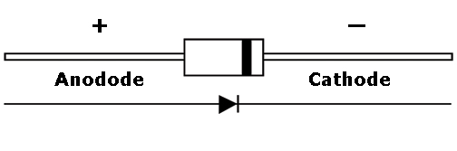
Diodes: Diodes are also directional
and must be installed properly. Their primary function is to insure
the flow of current is only in one direction. This symbol ![]() is
used to indicate a diode in a circuit diagram. Current flows from the
cathode side to the anode side. If they are installed with
the polarity reversed, your pulser will not work. The stripe on any
diode indicates the cathode side and the negative pole.
is
used to indicate a diode in a circuit diagram. Current flows from the
cathode side to the anode side. If they are installed with
the polarity reversed, your pulser will not work. The stripe on any
diode indicates the cathode side and the negative pole.
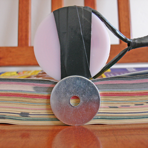
About flying fender washers: My washers don't fly up from the center of the coil as with some other designs. Washers on my unit fly in line with the sides of the coil. When experimenting with this, one needs to play around with the magnetic field until one finds the right spot. Once I figured out the correct positioning for the washer, I was able to get a 1-1/2 inch fender washer to soar about 40 inches into the air. Pretty amazing!
Starting my Pulser for the First Time: I didn't know what to expect when I plugged the chord into the outlet and pressed the on switch for the first time. The lights came on momentarily and then went out. Chris Gupta told me this was normal.
Should you build your own machine based on this design, and after turning the unit on, the lights come on and stay on, immediately turn the machine off and troubleshoot your assembly! Also if the lights don't come on at all, then something is amiss as well. I had rubber gloves on when I pressed the push-to-make switch for the first time. When pressing the push-to-make switch the lights shown brightly and I could hear a slight momentary sound from the wires in the coil. Again, Chris said this was normal. All was well and I had successfully built my pulser. After repeated pulses, the coil will begin to get warm. This too is normal.
Note: Always press and instantly release the push-to-make switch. The circuit is designed for repeated but momentary bursts of electromagnetic pulses. Keeping the push-to-make switch depressed will damage your pulser.
One should consider saturating the induction coil with some kind of resin and let it cure, to prevent the wires inside the coil from moving when the machine is discharged. The movement of wires inside the coil is in effect wasting energy that could be converted into electromagnetic energy. Also, such movement over time can cause the insulation of the magnet wire to wear through, and cause the coil to short out internally. I purchased a large bottle of super glue available at most hobby stores and poured a substantial amount into the coil. I then sprayed a little super glue catalyst onto the coil that made the glue cure instantly on the surface. The catalyst is also available at the same hobby shop where the glue is purchased. The catalyst is very handy to speed up the curing process. I still let the coil sit over night before using it, to make sure all of the glue had cured on the inside. Be careful when doing this, because super glue will instantly bond skin. Also one also doesn't want to inadvertently glue the coil to whatever it is sitting on. Use acetone for cleanup
Chris Gupta's Instructions and parts List:
Well finally, I (Chris Gupta) have got all the wrinkles out my prototype SCR Thumpy. And this circuit has definitely got the power. You can actually feel an electric current pulse when used in the neck area - uncanny! This is subtle however. I hasten to add that power is not the be all and end all, indeed, it is quite possible to design very effective low power pulsers with exceptionally fast pulse rise times that can surpass the performance of even the most powerful pulser. Unlike the high power pulsers these minimize dangers from electromagnetic radiation. So be warned and don't get carried away with the lure of high power! It has been long known amongst alternate energy and electromedicine researchers that very high speed pulses have the ability to tap into some form of radiant energy that is generally not recognized by mainstream science. Devices with very weak but high speed pulses in nanosecond range have been build and efficaciously used by NASA engineers. This is a well known phenomena and I have worked it out mathematically to my satisfaction. More on this at a later date. One theory is that such weak high speed pulses are able to by pass the cell electromagnetic defenses by their sheer speed but certainly there are other issues a play such as tapping radiant energy... For a better description on this please see Dr. Glen Gordon's video here (Dead Link, Sorry!). Dr. Gordon was a candidate for a heart transplant but managed to rebuild his own heart by just such a device.
See also: BIOELECTROMAGNETIC MEDICINE - THE BOOK
Please note that this is not a permanent magnet but a pulsed magnet and as such the polarity is not an issue, when the pulse collapses the magnetic field reverses. Hence one need not worry about the magnetic polarity.
I still don't like the auto-pulsing types as the body gets habituated to non random pulses the only exceptions are possibly the natural beat frequency of the Earth magnetic field (9.6 Hz) AND the Schumann waves (7.83 Hz) - a random pulser circuit is still the goal but due to great demand, much against my will, have now included a constant pulsing option for those who requested it. For the sake of simplicity a neon lamp is used. Unfortunately neons are not very stable and tend to vary as time goes by and may need to be replaced so use a socket for a quick change. The pulsing rate can be changed and should be changed every so often so the body does not get habituated, to that end I have added a switch to change the pulse rates...
To calculate the output energy use the following:
Formula: W=(CE^2)/2
W=energy in joules: C = Capacitance in farads: E = Voltage across Capacitor in volts
More on Capacitor Charge Calculation re.
Any SCR with PEAK current of at least 600 to 1000 amps should work. The one shown is 20 amp continuous with the appropriate peak rating. The lamps act as current limiters and protect the SCR against a short circuit. The circuit can be further simplified as discussed in point 3 below.
Steffan's Note: We recommend an alternate SCR! Please See My SCR Recommendation Above.
I have build several of these and my experience has been:
1) The capacitors develop a memory and don't fully discharge its better to use a number of them in parallel. This reduces the internal resistance and provides a better result and less memory loss. The caps must be designed for flash applications. They need not all be the same value but must be the minimum voltage rating stated.
2) In the original Beck based designs the flash tube heats and develops some resistance so you need to have enough time between flashes for them to cool down. This has been eliminated in my circuit, however, you still need some time for the capacitors to charge up. The larger the capacitor bank the longer it will take to charge up. Those planning to incorporate the automatic version must be mindful of this and adjust the timer circuit to compensate this effect.
3) Using a high current SCR (forces the caps to fully discharge by providing a longer connection than the strobe) and parallel caps from disposable cameras I can now consistently get 12 - 18 inch jumps with #14 fender washers. You can cycle them very fast (though not recommended). All for less than $30 to $50 Cdn. The most expensive part is the coil which can cost as much a $20 unless you build it yourself! One can further reduce the cost if at a latter date you don't want to upgrade to auto pulsing. This can be accomplished by removing the 10k resistor and the SCR and by simply wiring the a push to close switch in line to the coil. Don't recommend this unless you just can't get an SCR or really need to reduce cost. MAKE SURE THE PUSH BUTTON SWITCH CAN HANDLE THE CURRENT AND IS MECHANICALLY ROBUST!
Steffan's Note: These instructions were written 20 years ago. Disposable cameras are no longer a viable option for getting capacitors. Use a single Rubycon 450V 600uF PhotoFlash Capacitor (or equivalent). Available on eBay.
More info regarding other coils options etc. is available from the keelynet website.
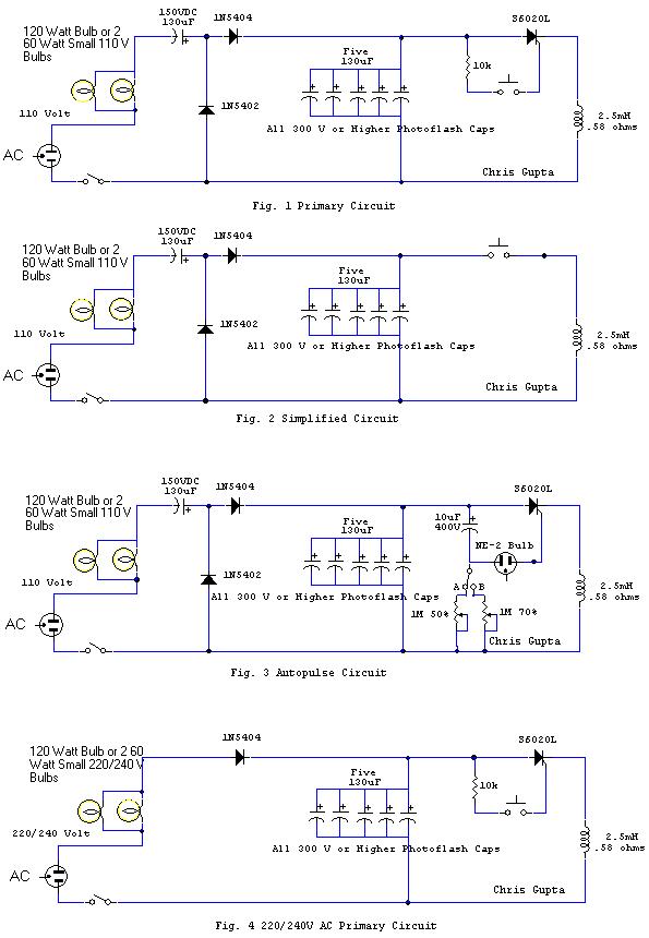
NOTE: I'm mentioning it again here. The bank of 5 capacitors shown in the diagrams below
should be substituted for a single 450V 600uF photoflash capacitor.
Those interested in using a 12 VDC source use a cheap 75 watt car inverter I bought one on sale for just $7 Cdn! Simply remove one of the bulbs. This of course is easier if at least one bulb is in a socket.
Steffan's 220V Recommendations
Not for US Style 220V where 110V + 110V = 220V)
Voltage source must provide a single 220V/240V Positive connection and a single
Neutral or "Return" connection.
NOTE: According to Russ Torlage of Sota Instruments, a minimum of 330V is required to generate a 6000 gauss magnetic pulse though a 2.5 mH air core inductor coil (either 18 AWG or 16AWG). Torlage also indicated that a 6000 gauss pulse was the minimum necessary to create the subcutaneous micro-currents needed to kill pathogens. If this is correct, neither Gupta's 110/120V or the 220/240V circuits are able to produce the desired voltage. That is why here in the USA I have incorporated 115V -> 230V isolation transformer. The I use Gupta's voltage doubler to boost the charge voltage to 360V. When building the 220V mag pulser, use the 220V bulbs as Gupta recommended, but otherwise follow the wiring diagram in figure 1. Voltage will then get doubled to a minimum of 360V plus or minus. Be sure the diodes and capacitors you use are rated for the high voltages! C1 should be rated at least at 300V and C2 should be rated at 450V-500V depending on the output from the voltage doubler. Silicone rectifier diodes should be rated at least 600V, 10amp.
To assemble the 220V mag pulser follow steps 1 and 2.
1.) Capacitor C1 needs to be in place and be rated 330V @ 150-160 MFD (Refer to figure 1). A 330V/160MFD photo flash capacitor would work well in this location. Search ebay.
2.) The value of the 2 diodes should be increased to 600V 10 amp (Refer to figure 1) for placement.
3.) For C2 use 1 Rubycon 600 MFD 450V photo flash capacitor. Can be found on eBay. (Refer to figure 1).
4.) Make sure the SCR is rated for 1000V.
5.) 10k resistor should be increased to handle the higher voltage. I would start with a .5W 30k resistor and see if the there is enough current to trigger the gate on the SCR. If no, then drop down to 20k.
Capacitors can now charge to over 360V+ and the electromagnetic pulse will be substantially more powerful. The longer one lets the capacitor charge, the higher the voltage and the stronger the pulse. Expect a full charge in about 3-4 seconds or when the light bulbs go out completely. The voltage charge in the capacitor will of coarse reach its maximum at around 360V.
This modification will only work with with Gupta's "MANNUAL", push button mag pulser design. I have not worked with Gupta's auto pulsing circuit, so I can't be of any assistance there.
NEW INFO! Here is a schematic for an auto-pulsing Bob Beck style mag pulser with a neon indicator light. The original schematic was made by Bill Green. Based on my own experience with this circuit along with recommendations from Russ Torlage of SOTA Instruments I have made a couple of modifications. One may have to play around with the value of R5, but start with a 680k resistor. The circuit I use has a few more modifications and charges to 360V. I will post that schematic below. It's a combination of Gris Gupta's circuit and this one. Notice the direction of the MR756 rectifier. This is to prevent reverse voltage from damaging the C1.
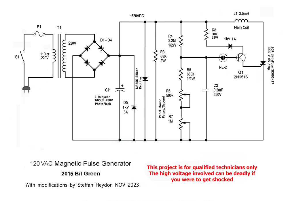
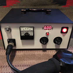
As Promised, here is the mag pulser circuit I use —
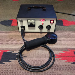
As stated above, it's a blend of Gupta's mag pulser circuit and Bil Green's along with modifications of my own. I use a 115V to 230V isolation transformer. Even if you have 220V in your country, you still need to use a (1-1) isolation transformer for protection. This circuit works really well. I have it built into a metal enclosure and I have a small cooling fan installed. Components used that are not included in the schematic are the digital timer relay (see below) and an analog 500V DC volt meter.
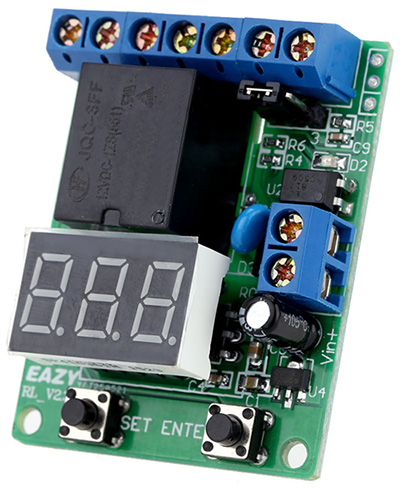
The digital timer relay operates at 12VDC and requires a 120V -> 12V step down transformer and a bridge rectifier. I used to buy this timer off of eBay but I don't see it for sale there anymore. I did find a company in China that still sells this model. The relay is durable enough to be able to switch the 120V line voltage coming into the machine. It's the only digital timer of it's kind that I could find where one can unplug the LED module and relocate it. I need this function because in my mag pulser the timer PCB is mounted to the main circuit board and the LED is mounted to the control panel. Click on image to go to web site. I preset the timer to 600 seconds (10 minutes). A small momentary switch (not included) restarts the timer.
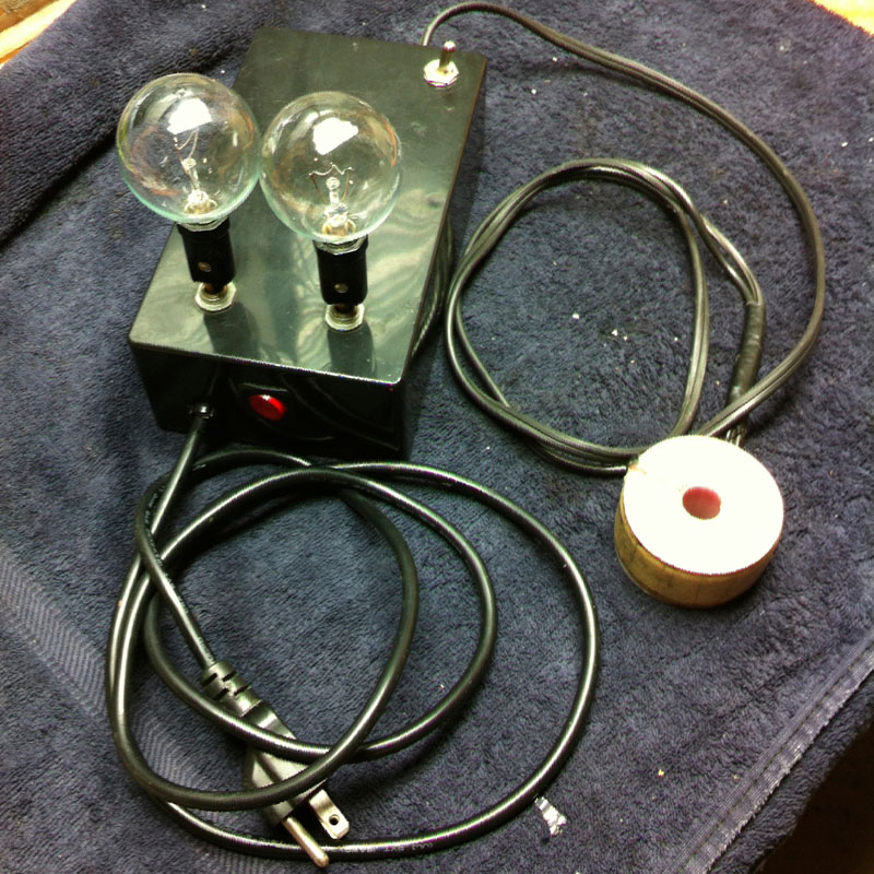
My Very First Magnetic Pulser Info and Photos
Based on Chris Gupta's 120V Mag Pulser Design with modifications.
March 28, 2015
Please post any successes, failures, comments
or questions on on my FaceBook Page. ![]()
Some individuals have posted
claims that Chris' design is flawed. I for one, can attest that his
design is sound and works well. If after constructing your device it fails to work, it is most certainly an error in construction. If your device does not work, the capacitor polarity may be incorrect, one or more diodes may have incorrect polarity, a component may be burned out or defective, or there is an error somewhere in how things were assembled and soldered. Watch for any arching on your component board.
My bulbless, variable speed auto-pulsing Bob Beck mag pulser is here!
Price $1300. For more information and to purchase this device please click on This Link.
Page Last Updated December 16th, 2023